
This week's Fab Academy assignment was electronics production: routing a PCB and populating the board with components to produce a FabISP, that is a wee programmer board for programming AVR microcontrollers.
Vcarve is normally great at tracing from a bitmap image such as the .png provided. However it wasn't playing ball for me so I ended up tracing it in Illustrator and exporting a .ai that Vcarve did feel like reading. This method led to a slight error as I'll detail later. (The importing problem solved itself when we restarted the machine later).
So we milled ours using a 0.15mm V shaped engraving bit which gave better results (as suggested by other lab members). I pocketed the routing, so that the mill removed all bits of copper on the board not needed, rather than just cutting the profiles of the traces. I was being cautious with cutting speeds so this did take some time, which we will have to work on (and indeed Loraine managed to get the time down significantly). I was using a feedrate of 4mm/sec, cutting to a depth of 0.15mm, so needing 2 passes as my board wasn't very flat having been taped to a piece of plywood.
I then used a 3.1mm endmill to cutout the board, and went for a way too conservative speed of 1mm/sec with a depth of approx. 1mm. On top of that, we found that Vpanel (the live controller program for the mill) was showing that the mill was cutting much slower even than the speed I specified. The reason for this was the new settings not propogating properly in Vcarve, so I learnt a new quirk of the program there. (Basically, to update tool settings you have to change to a different tool and back again and update the settings).

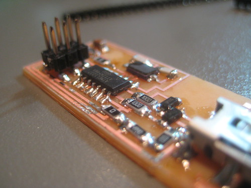
As you might be able to see, my illusrtator traces resulted in the loss of one pad at the USB socket (thankfully it was one of the mechanical pads, rather of any electrical significance) and a little notch being taken out of the perimeter of the board also at the USB socket. The former was fixed with a little superglue at the end.
I found the following soldering method generally worked well for me: Using a flux pen on all pads, then applying solder to the first pad of the component. I then pressed the component in place and on top of that solder and reflowed the solder to tack the component down on its first leg. I then could solder remaining legs almost as normal, albeit with much less solder and occasionally cleaning up with braid. By far the trickiest was the USB socket legs, which I couldn't get flush with the board properly.

Setup
We are having much trouble getting Ubuntu into use in the lab, for various reasons, and most advice has been against attempting to get Fab modules running under a Windows machine that is not online, which is the machine we have connected to the Roland Modela MD40 in MAKlab. So we went with a workflow the experts in the lab are much more familiar with, which is using Vcarve.Vcarve is normally great at tracing from a bitmap image such as the .png provided. However it wasn't playing ball for me so I ended up tracing it in Illustrator and exporting a .ai that Vcarve did feel like reading. This method led to a slight error as I'll detail later. (The importing problem solved itself when we restarted the machine later).
Milling
Thomas had attempted the milling first and found our endmills were not great for the task, burring up the copper quite badly. We were also lacking a really thin one for getting between the traces in the FABisp layout.So we milled ours using a 0.15mm V shaped engraving bit which gave better results (as suggested by other lab members). I pocketed the routing, so that the mill removed all bits of copper on the board not needed, rather than just cutting the profiles of the traces. I was being cautious with cutting speeds so this did take some time, which we will have to work on (and indeed Loraine managed to get the time down significantly). I was using a feedrate of 4mm/sec, cutting to a depth of 0.15mm, so needing 2 passes as my board wasn't very flat having been taped to a piece of plywood.
I then used a 3.1mm endmill to cutout the board, and went for a way too conservative speed of 1mm/sec with a depth of approx. 1mm. On top of that, we found that Vpanel (the live controller program for the mill) was showing that the mill was cutting much slower even than the speed I specified. The reason for this was the new settings not propogating properly in Vcarve, so I learnt a new quirk of the program there. (Basically, to update tool settings you have to change to a different tool and back again and update the settings).
As you might be able to see, my illusrtator traces resulted in the loss of one pad at the USB socket (thankfully it was one of the mechanical pads, rather of any electrical significance) and a little notch being taken out of the perimeter of the board also at the USB socket. The former was fixed with a little superglue at the end.
Populating ('stuffing') and Soldering
This went better than I had expected, being very familiar with thru-hole soldering and very scared of surface mount soldering (I have not steady hands). Being organised and methodical, using tweezers, good light, a magnifier and a PCB vice were all essential.I found the following soldering method generally worked well for me: Using a flux pen on all pads, then applying solder to the first pad of the component. I then pressed the component in place and on top of that solder and reflowed the solder to tack the component down on its first leg. I then could solder remaining legs almost as normal, albeit with much less solder and occasionally cleaning up with braid. By far the trickiest was the USB socket legs, which I couldn't get flush with the board properly.
Improvised headers
The headers required some improvisation as we couldn't get the surface mount headers specified, and they are seemingly almost impossible to find through big UK suppliers. Mine I made using straight thru hole headers, superglued together and the bottom legs bent outwards using pliers and shortened with wiresnips. Quite neat in the end.

No comments:
Post a Comment