Tuesday, October 08, 2013

Tchai Ovna sandwich boards


I was commissioned to make new sandwich boards for the Tchai Ovna House of Tea, a business which I have been orbiting and landing at in various forms all the time I've been in Glasgow..

For these we went for a method of painting that would allow me to do a batch of 6 panels as easily and efficiently as possible, whilst providing a very high finish. Whilst I'd like to learn hand brushed calligraphy for signwriting, I've not done it yet! So here we have 6 panels of 18mm spruce ply, laser engraved by Flux Laser Studio to 2mm depth, back filled with acrylic paint in 3 different colours, and then sanded back to reveal the sharp edges of the engraving. This is a method I learnt from the students in Dundee, clever chaps. They were then finished with wood preserver and yacht varnish, plus galvanised and stainless steel fixings. Not shown here, I gave the feet of the panels some little inner tube rubber booties, to repel the puddles..

The lasering process means the layout is on file and the boards can be reproduced very easily when they inevitably reach the end of their life or are half inched by the west end student contingent, of which I am a proud alumni!

Thursday, September 19, 2013

Wednesday, September 18, 2013

Big N for Nilk

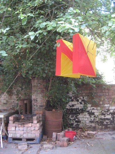
Last week was Nilk, the finest day of music and arts to be had in Dundee's Botanic Gardens. I was asked to make a big decorative N for the event - I ended up making one inspired by box kites, to be hung from a tree. Here it is rigged up in the courtyard of the studios:


The form is a bit of a geometric fun: the N is viewable from both the front and below, thanks to Rhinoceros, Boolean intersections and the UnrollSrf command, which can lay out all faces of a 3D object flat for you to make cutting patterns from!

The thing is constructed out of ripstop nylon offcuts (from the magnificent GPA) and bamboo stakes (from the gardening shop), sewn and cable-tied together, plus a little insulation tape. Many thanks to Fergus for his advice here, I'd never have guessed that insulation tape sticks so well to bamboo and not to nylon! 

I couldn't make it up there for the day sadly, so I made an Instructable as installation instructions here.

Another photo instructable gives an account of the making of here.

Some more photos from the installation:


Upcoming workshops at MAKlab

Some new workshops we (Myself, Aziz and Delphine) are coordinating at MAKlab over the next few weeks, including Using the Terminal in OSX and linux, Have a Go at 3D Printing, Make  Robot Bug and Toy Hacking workshops!
Check them out at http://www.maklab.bigcartel.com/

Monday, September 02, 2013

The Den

I was asked by theatre maker Jen Edgar to help her refresh the Sensory Room in Calderside Nursery, South Lanrakshire, where Jen was doing a residency in 2012-2013. It was a great experience, a very interesting project involving lots of den making, mocking up environments for the kids to try out, trying to understand what they made of it, and then wrestling with lots of fabric, an overactive heating system, and a little electronics to make the finished sensory room: The Den. The result is a much more welcoming and curiosity piqueing room, with a custom sound track by Scott Twynholm, and a big button that the babies can press to trigger sounds themselves on the immersive sound system. Lots of sewing and laser etched signs from me, as well as building some furniture and specifying electronics, on a very tight budget.


Here's the team, me failing to look at the camera.

Above photos by Neil Thomas Douglas

Tutoring Services: Arduino @ GSA

In January 2013 I consulted as an Arduino tutor at the Glasgow School of Art. I provided some refresher tuition and project guidance for 3rd year Product Designers there. The teaching materials are viewable here.

The project the students worked on was based around sound, and there were some great ideas being worked on. Most involved PIR sensors triggering sounds from a laptop (despite my attempts to discourage this for the absolute beginners). We mostly did this using the keyboard hack I described here. My favourite projects as ever were the mechanical ones however..

Ling's Meadow

Logo design for my sister in law's campsite, Ling's Meadow! I'm also making a stamp to go with this.


Yarla and the Winter Wood

Here are some production shots from Yarla and the Winter Wood, a touring theatre production for 0 - 3 year olds, for which I did the set design and build, and some prop making. You can read more about the production here, which was made by Jen Edgar for Starcatchers. Many thanks to Fergus Dunnet for his hard work, particularly in scenery painting.

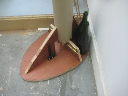
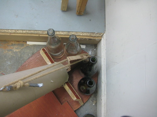
We used a lot of found items for the props in this, and the trees themsleves are carpet tubes from Victoria Road carpets (thanks go to them). The brief was to design a flexible set that could be reconfigured as the venue allowed (venues ranged from libraries, to nurseries, to theatres), and be mountable and demountable in 2 hours. The entire set fitted in a transit van and was handleable by the touring company of 3. There are lots of great photos from the development on Jen's blog here.


Above photos by Neil Thomas Douglas


Totem plinths - design & build

In September 2012 I designed and built a plinth system for the I Am Seeing Things exhibition at the Talbot Rice gallery in Edinburgh. This was an exhibition linked to the ToTEM project I was previously involved in, and included a seminar marking the end of the project. The brief was to produce a 3D pixelated system, of modular construction (read voxels), including several interactive cubes, containing monitors and the same tech as the previous ToTEM readers.

Construction was done in expanded polysterene, and selected voxels in MDF, all clad in white or grey melamine, placed on plywood bases.

This was a collaboration with the Product Research Studio in Dundee DJCAD, with especially thanks to Sean Kingsley there. Laser cutting (circa 500 melamine panels!) was done by me at MAKlab. Here are some photos of the results from around Twitter:

Upon delivery, prior to construction - photo by @chrisspeed

photo by @ileddigital

5th dimensional camera by Superflux - photo by @digitalurban

photoBot by Tommy Dykes - photo by @digitalurban

Interactive reader cube, front of picture - photo by @ileddigital

Wednesday, August 07, 2013

Sing for your Stitches

I had a great weekend some weeks ago at Culture Hack Scotland 2013, my second Culture Hack. I worked with Jude Wylie, Deidre Nelson and the amazing Yann Seznec, plus with a little help from Mark Craig we successfully hacked a sewing machine into a voice operated one! Sync wrote a lovely article about it here, where there is also a wee video. We were inspired by Hanna Tuulikki's Away With the Birds.

image by Chris Scott

Friday, August 02, 2013

Fab Academy: Final Project


An interactive mammoth toy - a modern update of a classic kids' model

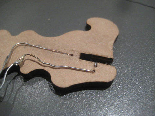
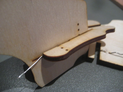
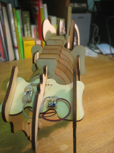
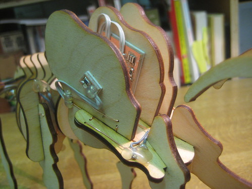
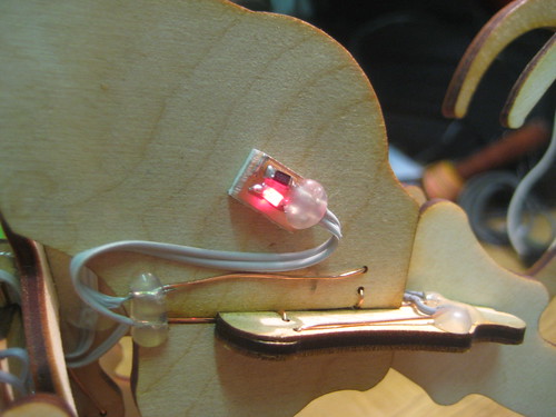
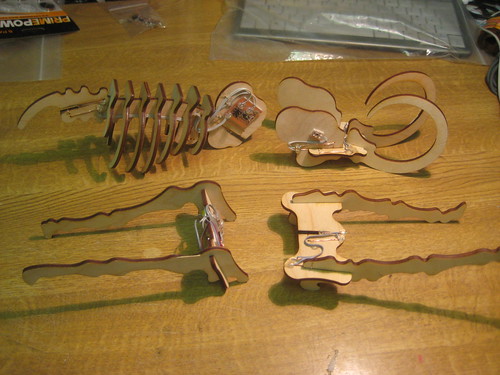
I started out by planning specifically which how to split up my dinosaur kit into differentelectronic system components. I decided to use the mammoth as a prototype, and studied the shapes of all the parts available and where would make most sense to place, the input, outputs, microcontroller and batteries. This was a more complex process than I had imagined, as the number of connections between each of these components has to fit with the number of physical connections on the host 'bone' of the mammoth. Furthermore, each connection has to make two electrical connections: ground and live. So I set about trying to work out a simple way of achieveing this, coming up with a system of wirefixed into holes in the ply wood and running through the slots where the bones fit together:


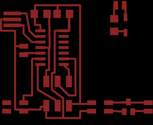
I then designed my board. I decided to keep things simple, and let the input be a tilt switch and the outputs being some flashing LEDs for the eyes of mammoth. Thus I started with the hello world board with button and LED, and pulled out these components and built in pads such that these could be easily connected to the inter-bone connectors. I also wanted the thing to run off batteries, so put in a small board for a regulator should it be needed. The total list of boards was thus 1 controller board, 1 regulator board and 2 LED boards. Here is the EagleCAD board and schematic.

There's a typo above, that should be a 499 Ohm resistor next to the LED, not 499K Ohm.

Here is the cutting layout:


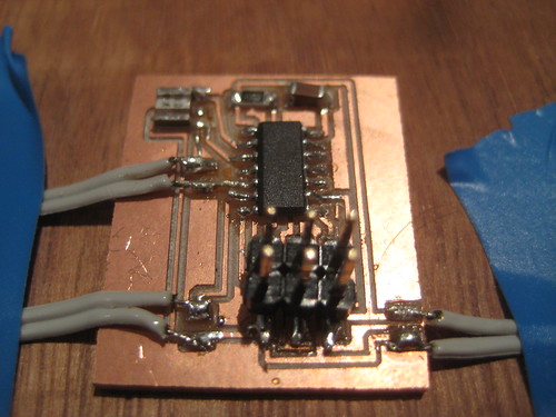
Milling the board was straightforward. Populating them was a little trickier as I'd kept everything quite small and tight, and soldering wires onto the pads leading to the connectors was particularly tricky. A through hole arrangement would work better, or using some low profile terminals of some sort.
Here is the finished circuit laid out on a wooden board temporarily:


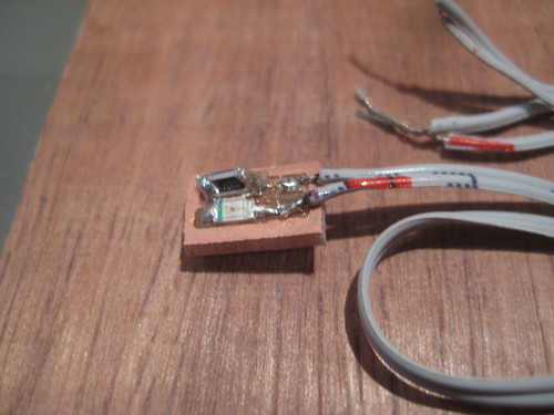
Here is one of the LED boards ( to be eyes), with a correcting 499Ohm resistor soldered on top of the too large one!:


Here is the very small controller 'brain'


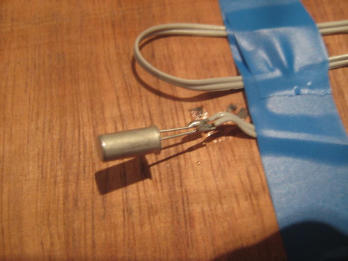
And here is the tilt switch to be mounted on a leg:


I had a bit of a hard time programming the board until I realised I didn't need to worry about serial ports for this - I was confused as one wasn't showing up, but hadn't realised that this does not happen when using the programmer alone. The code was made in Arduino, here it is:

/*
The circuit:

* LED attached from pin 8 to ground 

* pushbutton attached to pin 7 from +5V

created 2005

by DojoDave 
 modified 30 Aug 2011
 by Tom Igoe
 
 This example code is in the public domain.
 
 */

// constants won't change. They're used here to 
// set pin numbers:
const int buttonPin = 7;     // the number of the pushbutton pin
const int ledPin =  8;      // the number of the LED pin

// variables will change:
int buttonState = 0;         // variable for reading the pushbutton status
//#include 
//#define rxPin 0
//#define txPin 1

// set up a new serial port
//SoftwareSerial mySerial =  SoftwareSerial(rxPin, txPin);

void setup() {
  // initialize the LED pin as an output:
  pinMode(ledPin, OUTPUT);      
  // initialize the pushbutton pin as an input:
  pinMode(buttonPin, INPUT);
  digitalWrite(buttonPin, HIGH);    
// Open serial communications and wait for port to open:
//  mySerial.begin(4800);
//  mySerial.println("Hello, world?");
}

void loop(){

  // read the state of the pushbutton value:
  buttonState = digitalRead(buttonPin);
//mySerial.println(buttonState);
  // check if the pushbutton is pressed.
  // if it is, the buttonState is HIGH:
  if (buttonState == HIGH) {     
    // turn LED off:    
    digitalWrite(ledPin, LOW);  
  } 
  else {
    // flash LED on:
    digitalWrite(ledPin, HIGH);
    delay(500);
    digitalWrite(ledPin, LOW);
    delay(500);
    
  }
}

I rigged up the circuit with a power supply and it worked fine, but with a 3v button battery it seemed to struggle. I thus decided to use two button batteies and a 3.3v regulator, which produced good results. In order to save battery I also put in a slide switch  so that the user can switch off the curent to the regulator when not in use. Here is a video of the sensor temprarily rigged to a draft mammoth, and the prototype connectors:


Finally I got onto the laser cut mammoth itself. i had to clean up the file that I'd started with, so largely redrew it in Illustrator to make the slots much more consistent and reliable. I then had to add in some holes and engraving details so that the wire could be embedded into the ply for the connection points. I did this in Rhinoceros, as it is way better for doing things that are not strictly orthogonal! Here is the final layout as a .svg.


I then got onto cutting, and made a series of teests to ensure the fit was just right with the thickness of ply I was using (3.2mm).


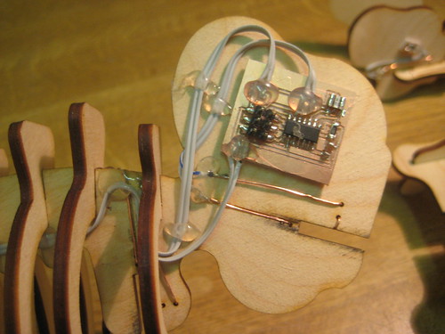
When I was happy with this, I went for a full cutting layout, assembled the mammoth and went about embedding the wire connections into each piece, and fitting the electronic parts to the appropriate pieces, using doublsided foam and hot glue to fix things in place. This took a wee while.


And here's a video of the finished product working!


Download all the source documents as a .zip here.

Tuesday, July 30, 2013

Some fruit of today's labour

a wee Processing effort from the Hack'n'chat with Ira Greenberg in Dundee today:


Monday, July 22, 2013

Frog on Industrial Design

Tom put me on to this great film from Frog Design and unusually good interview (for Core77) with Jona Damon of Frog. I'll embed the film below, but do click through to the interview as Damon's thoughts on the few bits of Rams' 10 principles that may no longer be so relevant, make very interesting reading.


PS. Annoyingly I can no longer use my 'design thinking' tag for stuff like this as it has been usurped by a less obvious and more irritating meaning (for which I think 'designer thinking' would be a better term). So will think of a new tag.

Sunday, July 21, 2013

Fab Academy: Interface and Application Programming

I used Anna's example 1 here as a basis for exploring some interface design using my input boards - the light sensor and temperature sensor. The example worked pretty much out of the box and was well commented so was a good way to understand some Processing - I had to edit the code initially to ignore sensor values below 10 (it seemed to spit out a proper reading every fourth time, and these small values the rest of the time). This was already in the code to a certain extent - it didn't draw a line for those values, but it did cycle onto the next column for them, so the result was an unsatisfying sparse bar graph, rather than a nice band of colour. All I had to do to rectify this was move the part of the code that moves into the next column

   col = col+1;

into the if statement that ignores the small values and draws a vertical line:

    //if the serial values are greater than 10
    if (height > 10) {
      //draw a line that increases / decreases based on sensor output.
      //adjusted for sensor values.
      col = col+1;
    if (col > 1024) {
      col = 512;
    }

I then edited the code so that rather than printing out vertical lines in a band across the screen, the program draws ellipses. These change shape according to the values from the sensor, and colour according to these values too, as well as time.
Here is the key bit from the code for what I eventually settled on:

    stroke(255-height, col/4, height, height);
    fill(255-height, col/4, height, height);
    ellipse(512, 512, 3*height, 3*(255-height));

where height is the name of the variable that the sensor reading is read into.

My friends Mark and Nathan also showed me how to use some transparency to great effect. The last of the arguments after stroke and fill there corresponds to transparancy, which I also made equal to the sensor reading ('height').


Here's the full Processing sketch:

/**
 * Serial Input to Randomly Colored Lines
 *
 * Read data from the serial port and changes the color of a lines drawing
 * across the screen the height of the lines changes relative to the values
 * recieved from the sensor.
 *
 * written by Shawn Wallace
 * updated / commented by Anna Kaziunas France
 */

import processing.serial.*;

Serial serialPort;  // Create object from Serial class
int col = 512; //starting point for the lines on the screen

void setup() {
  size(1024, 1024); //set window size
  background(0); //set background color to black
  stroke(255);  // set stroke to white
  smooth(); //smooth out the lines

  // I know that the first port in the serial list on my mac
  // is always my FTDI adaptor, so I open Serial.list()[0].
  // On Windows machines, this generally opens COM1.
  // Open whatever port is the one you're using.
  println(Serial.list());
  serialPort = new Serial(this, Serial.list()[0], 9600);
}

void draw() {
  //if there is data comming in from the serial port
  while (serialPort.available () > 0) {
    //set the variable height equal to the data comming in.
    int height = serialPort.read();
    //to draw rows across the screen in columns
    //then wrap back to other side of the screen
 
    //if the serial values are greater than 10
    if (height > 10) {
      //draw a line that increases / decreases based on sensor output.
      //adjusted for sensor values.
      col = col+1;
    if (col > 1024) {
      col = 512;
    }
    fill(0,0,0,10);
    rect(0,0,1024,1024);
    stroke(255-height, col/4, height, height);
    fill(255-height, col/4, height, height);
    ellipse(512, 512, 3*height, 3*(255-height));
    //line(col, (height-125)+512, col, 512-height);
    //line(1024-col, (height-125)+512, 1024-col, 512-height);
    println(height);  //print the values read from the serial port to the console
    }
    //EXPERIMENT WITH THE VISUALIZATION BELOW
    //currently draws random strokes for the full range of color
 
  }
}

Fab Academy: Computer Controlled Machining

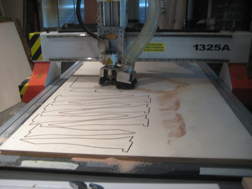
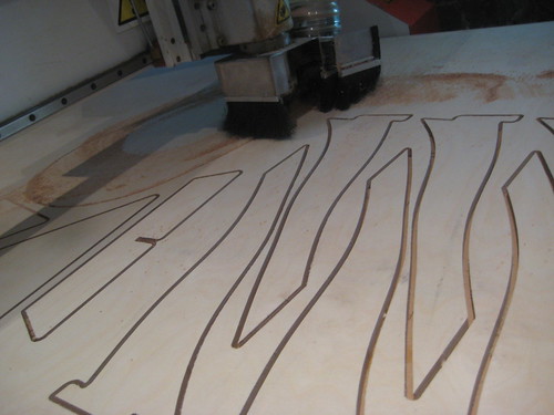
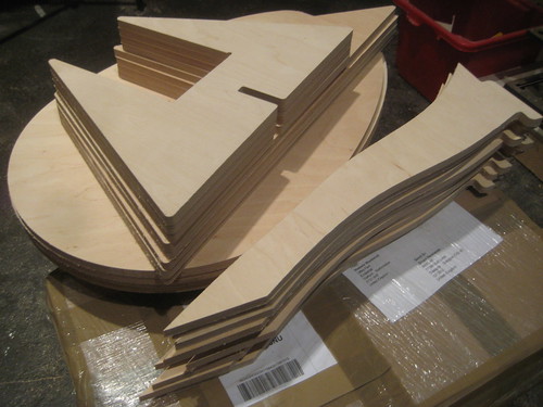
Following on from the cutting layouts that  generated previously, I routed out numerous parts for the set for Yarla and the Winter Wood - namely the bases and branches for 11no. 2.4m trees. The trunks of the trees were made from cardboard tubes, the sort that carpets are rolled around for delivery.

I imported the layouts in .dxf format into VCarve Pro. In this I generated cutting paths for the large router table that I would be using. I used my own 1/4" router bit, and used the speed settings recommended by the lab. From this I exported a .nc file of Gcode.


At the router table, we made sure it was swept clean, and screwed a 12mm ply sheet to the sacrificial sheet below. This router table has a vacuum bed, which keeps the sacrificial sheet down, but one still needs to secure the cutting sheet on top of this as the vacuum does not extend above the sheet! For each cutting layout I took care to measure of the layout and mark on the sheet safe zones for screwing near to each corner, so that the router head would not risk hitting any screws.


On the first attempt at cutting we quickly broke my router bit. it turns out that the bit I had was longer (25mm) than that which the setting we used were for (about 15mm), hence the feedrate was too fast for it. I switched to the shorter length bit, used the override function in the control software to cut at 70% speed, and had no further problems.

When importing Gcode from VCarve into our cutting software, we must delete the first two lines. Other than that, the software is very straightforward, and I made used of the simulation playback, to check that the job was setup correctly before commencing. In all I cut a lot of parts for the trees out of 3no. 12mm birch ply sheets in about 3 hours.

The slot together construction worked surprisingly well, with 12.1mm slots, creating a good snug fit. All the parts required a quick sanding on both sides to remove skelfs.
I found that a good way to separate the routed pieces from theirs tabs onto the board was using wome wire snips.


Fab Academy: Computer Aided Design

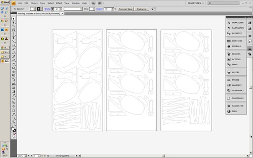
I recently made some artificial trees for a theatre production, Yarla and the Winter Wood for Edinburgh baby-theatre company, Starcatchers. The bases of these were CNC routed on our 8' x 4' bed from 12mm plywood. Here is how I went about generating the drawings for that.

First there were a few iterations prototyped by hand, using pencil and paper, and some 20mm blockboard that I had leftover in my studio. Because the trees are designed to tilt during the performance, the bases required a little bit of mechanical engineering. 


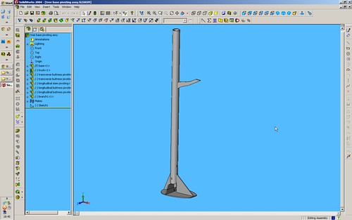
When I was happy with the design, I transferred to Solidworks, a solid modelling program. In that I drew out each part to be routed and put together an assembly to test that the geometry fitted, and that the tilting would behave as desired. I then used the drawings module of Solidworks to generate 2D drawings from projections of the 3D parts. I then exported a .dxf file from Solidworks into Illustrator for checking and nesting the required number of parts into the outlines of the 3no. 8' x 4' sheets that I would be using.


Thursday, July 11, 2013

Fab Academy: Invention, Intellectual property, and Income

I am a keen participant in open design culture so as such will distribute my final project as a fully open product, so that others may easily collaborate in its development. As the designs we already have for the dinosaurs were gleaned from CNC forums, it is unclear if they are under any license. Certainly they do not have any license information in the files themselves (this could of course have been removed by previous sharers). The raptor in particular appears to be quite a complex kit, implying that it might have once been a proprietary design. I plan therefore to not use that particular dinosaur design (there are probably too many parts to consider in any case), and to continue with the others. I anticipate that these designs will be used as a starting point in any case, and that the final designs will have undergone numerous changes.

In my experience the key barrier to actually achieving a collaborative open project, is in nurturing a community of users around the product. To this end, platforms like Instructables, Make and Thingiverse can help in getting your project seen and criticised. However, I have been quick to use these early on in the development process before, and found that my energy and interest in the project has waned before having achieved much collaboration with others. Indeed my most successful in this respect has been the first fully open product that I published, the Ten Green shelving, which was essentially a finished product when published.

So, my intentions will be develop the dinosaur kit to a basic finished level before promoting online, if only to make most efficient use of my time, and others' attention spans. In terms of income, I am happy to make some from markups on kits that I sell. However I would only be able to make them cost efficient if making a batch, so if I gauge that there is interest in buying kits, I will look at instigating pre-orders or a crowd funding project, or take orders from craft retailers in Glasgow. The kit may well also make a good basis for workshops that I can deliver in the future, providing some income, as well as educational and social benefit to the participants as a means of experiencing digital fabrication.

Wednesday, May 15, 2013

Fab Academy: Applications and Implications

Here is my project plan for my Fab Academy project: Interactive Dinosaur Kits

what will it do?

I am going to make a modular toy dinosaur kit incorporating some electronic behaviours. The kit is for 8-10 year olds and will allow them to freely construct their own dinosaurs, mixing body parts as they wish. The dinosaurs will be made by slotted ply construction, and copper vinyl at the interfaces will act as an electrical conduit between different body parts. Each body part will contain one element of the electrical circuit: one or more inputs, one or more outputs, processor, or power supply. For the prototype I will attempt to use 3 tilt sensor inputs and 2 LED outputs, and work onward to an additional output triggering an MP3 module, to play dinosaur sounds.

who's done what beforehand?

The principle of the kit owes a great deal to the classic dinosaur kits of my youth, as well as on the electrical side of things, Ayah Bdeir's Littlebits, and Yuri Suzuki's Denki puzzles. All of these examples brilliantly capture my aim of producing a simple, fun, educational kit, very elegant in presentation such that young minds can freely explore both the possibilities and constraints of a puzzle like kit, as well as simple electronic theory and ending up with a cool dinosaur at the end too.


what materials and components will be required?3mm Laser ply,

Copper vinyl,
Components for hello world board
3 tilt sensor inputs
2 LED outputs
MP3 module
Batteries

where will they come from?

3mm Laser ply - lab stock
Copper vinyl - Techsoft
Components for hello world board - lab stock
3 tilt sensor inputs - Rapid online
2 LED outputs - lab stock
MP3 module - Embedded Adventures
Batteries - my stock

how much will it cost?

3mm Laser ply, £5
Copper vinyl, £6
Components for hello world board, £3
3 tilt sensor inputs, £2
2 LED outputs negligible
MP3 module £16
Batteries £1
TOTAL: £33

what parts and systems will be made?

Physical dinosaur body parts (kit of)
One controller board, based on Hello World
Battery holder
Copper vinyl contacts 

what processes will be used?

Physical dinosaur body parts (kit of) - CAD and laser cutting
One controller board, based on Hello World, - milling, electronics production, programming
Battery holder - 3D printing or resin cast from CNC milled master
Copper vinyl contacts - CNC vinyl cut or handcut 

what tasks need to be completed?

Design and develop body parts from templates,
Test and develop slotting together using copper vinyl,
Develop integration of electronic components into body parts,
Design main circuit board,
Produce main circuit board,
Laser cut body parts,
Assemble electronic components with body parts,
Write code and upload to board,
Test first assembly
Iterate onwards, incorporating sound output.

what questions need to be answered?

What electrical implications are there for separating the various electronic components and what happens in all the combinations that they might be connected? Do those constraints fit with the pysical/geometric constraints of the kit/puzzle? 

what is the schedule?

As I am short of time anyway in the next few weeks, I am considering concentrating on completing previous week's assignments and tackling the final project after the course ends, in order to make the most of the tutor contact time I have remaining. This may well be ill conceived, in any case the general schedule will be:

Day 1:
Design and develop body parts from templates,
Try to answer those unanswered questions.

Day 2:
Test and develop slotting together using copper vinyl,
Develop integration of electronic components into body parts,

Day 3:
Design main circuit board,
Produce main circuit board,

Day 4:
Laser cut body parts,
Assemble electronic components with body parts,

Day 5:
Write code and upload to board,
Test first assembly,

Day 6:
Iterate onwards, incorporating sound output.

how will it be evaluated?

My criteria for success will be whether a child or range of children of 8-10 can understand and enjoy assembling the kit.

Fab Academy: Machine and Mechanical Design

For our team machine design project we are building a Fabscan 3D scanner for the new Strathclyde University Fablab. I have taken on the task of adapting (very lightly) the files for 3D printing (a laser holder and turntable component) and printing them. These are Openscad files, available here . I found an alternative turntable component on Thingiverse here, that looked better in design so decided to use this as a basis. Having not used Opencsad much, it took a wee while to decode what bits of the script did what. Thankfully a lot of it is commented both in English and German. The radii for holes are in particular easy to find at the top of the script as constants as in this example from the laser holder file:

lhIR = 6; //this is where you define the radius of your laser module!
lhOR = lhIR+6; 
lhH = 8;

shIR = 2.5;
shXS = shIR+2*lhH;
shYS = 2*lhOR;
shZS = 15;

nutY = 2.6;
nutZ = 5.6;

I did have to edit the radius of the laser module to match the one that we ordered here.

Having edited other holes to match our stepper motors, I was ready to print. This was fairly straighforward, being quite experienced with out Ultimaker. I did encounter a wee extrusion problem caused by our filament being tangled on the reel - required me to cut it free, untangle and reload the filament. The trick to this is to keep the nozzle temperature at melting point (228 degrees for our PLA) and manually run the extruder to make sure it is properly gripped.

Having printed the parts, I found that the holes for the stepper motor spindles in particular were a good mm too small, so redrilled them. I would recommend doing this in any case to ensure they are completely circular. This was less necessary for the larger laser module hole.

The parts are ready to be assembled into the machine - more soon!

Fab Academy: Networking and Communications

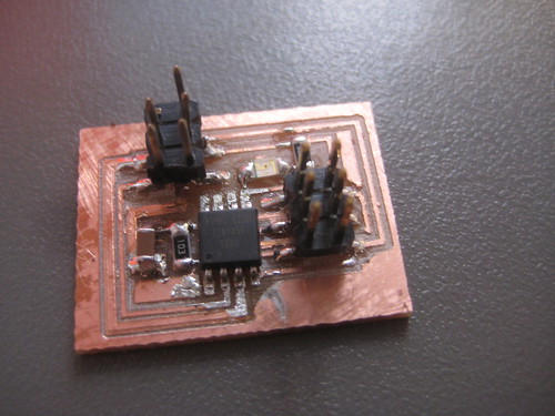
I had already made the boards for this week when I made my RGB LED board. These also had some of the milling problems described there however. Here is the bridge board:


and the node:


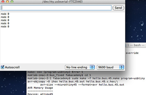
I have managed to program the bridge board and get it working using the Providence tutorial here. Here is the serial output from the board as I type 0 into the monitor:

I am having more trouble with the node however, it returning repeated rc=-1 errors. I have thoroughly checked the board and removed a lot of solder from the chip legs but still get the same issues so am still working on getting the whole network working.