I just put up an Instructable describing the production method for the Tchai Ovna sandwich boards here.

Showing posts with label digital manufacturing. Show all posts
Showing posts with label digital manufacturing. Show all posts
Friday, October 11, 2013

Tuesday, October 08, 2013
Tchai Ovna sandwich boards
I was commissioned to make new sandwich boards for the Tchai Ovna House of Tea, a business which I have been orbiting and landing at in various forms all the time I've been in Glasgow..
For these we went for a method of painting that would allow me to do a batch of 6 panels as easily and efficiently as possible, whilst providing a very high finish. Whilst I'd like to learn hand brushed calligraphy for signwriting, I've not done it yet! So here we have 6 panels of 18mm spruce ply, laser engraved by Flux Laser Studio to 2mm depth, back filled with acrylic paint in 3 different colours, and then sanded back to reveal the sharp edges of the engraving. This is a method I learnt from the students in Dundee, clever chaps. They were then finished with wood preserver and yacht varnish, plus galvanised and stainless steel fixings. Not shown here, I gave the feet of the panels some little inner tube rubber booties, to repel the puddles..
The lasering process means the layout is on file and the boards can be reproduced very easily when they inevitably reach the end of their life or are half inched by the west end student contingent, of which I am a proud alumni!
Wednesday, September 18, 2013
Upcoming workshops at MAKlab
Some new workshops we (Myself, Aziz and Delphine) are coordinating at MAKlab over the next few weeks, including Using the Terminal in OSX and linux, Have a Go at 3D Printing, Make Robot Bug and Toy Hacking workshops!
Check them out at http://www.maklab.bigcartel.com/
Check them out at http://www.maklab.bigcartel.com/
Wednesday, August 07, 2013
Sing for your Stitches
I had a great weekend some weeks ago at Culture Hack Scotland 2013, my second Culture Hack. I worked with Jude Wylie, Deidre Nelson and the amazing Yann Seznec, plus with a little help from Mark Craig we successfully hacked a sewing machine into a voice operated one! Sync wrote a lovely article about it here, where there is also a wee video. We were inspired by Hanna Tuulikki's Away With the Birds.


image by Chris Scott
Wednesday, March 13, 2013
Fab Academy: Casting
This week at Fab Academy: Casting


Silicone cast from PLA 3D print experiment
Prior to this week, I already made a wee experiment casting silicone into a mold that I printed back in the 3D scanning and printing week. I used cooking oil to ensure a release, especially as I knew the print was fairly messy in the cavity. I soon realised that oil can seep through the layers of even what looked like a watertight print, so I wouldn't advise this if you'd like to remain clean and tidy. Once the silicone had set, getting it out of the mold was fairly straight forward, except for the very bottom of the piece which was quite snarled up with the print. The object I am trying to cast is for a live project I am doing, and is basically a tube shaped component, so the mold requires a plug. In this first case I realised quickly that the silicone is too viscous to flow well into the 2mm wall cavity that I had created in the print, so I pulled out the printed plug and replaced it with a pen lid of the same diameter (having filled some holes in it with hot glue and oiled it). This plug popped out very easily but obviously the silicone was very snarled up in the tough edges of the print where I had ripped out the plug.

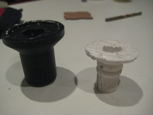
All in all the results were surprisingly good for me, having expected the cast not to release at all. Here is the printed mold and the silicone cast. I sealed the bottom of the mold with hot glue to stop all that oil seeping out everywhere! It is encouraging to know this method of casting is possible, as printing a simple mold is really quick, but the surface finish is always going to be as bad as that of the print. I wouldn't recommend it for thin walled things, unless you make a plug like I did.
Polyurethane Rubber cast in Silicone mold test
I ultimately wanted a much smoother surface finish, and wanted to try the polyurethane rubber, so I thought I'd use the interior of my silicone cast as a mold for a polyurethane rubber plug. I taped over the bottom of the silicone form with duct tape, mixed up some (black) PU rubber with some white pigment (resulting in a grey colour) and poured it in. The PU rubber is much less viscous than the silicone so is better for pouring, but it seemed to drain down fairly quickly which made me wonder if the tape was letting it leak around slightly (duct tape doesn't stick to silicone all too well). When i came back to the cast the next day, it had reduced in height yet more, which makes me think it might be shrinking quite a bit. When I opened up the mold I saw that sure enough the PU rubber had seeped in to the tape a fair bit. The resulting cast separated really easily from the silicone, having not had any release agent. A promising result for my next cast. Below is the silicone mold and the resulting plug - the PU rubber we have is really stretchy, possibly more so than even the silicone.


Wax master - Silicone mold - PU rubber cast
Whilst I was waiting for the previous cast to set, I milled a new master from machinable wax on the Roland Modela 40, using the rotary axis unit. This was a steep learning curve, especially setting up the rotary axis, but the results were great! The wax machines really well, and the rotary axis means we get a beautiful finish on small radii things. Quite limited in terms of workpiece size however - we are using SRP player, the Roland software, to drive the rotary axis, which has in built safety features forcing you to use a very long workpiece to keep the tool head far away from the rotary axis jig. Anyway, the results can be seen below:
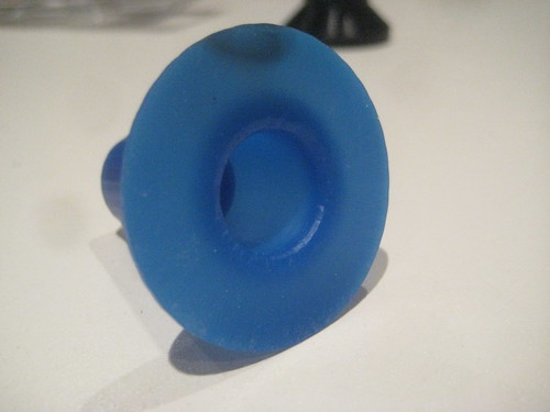
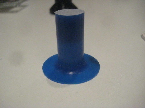
This is the workpiece after I had cut it off its supports and manually drilled the cavity through the middle using the pillar drill and a Forstner bit for the 15mm diameter hole.
I then used a cube from the pressfit assignment as a shuttered box to cast the silicone into, with the edges taped up. I placed a couple of small blocks of wax at the bottom as sprues, and placed my wax master on top.
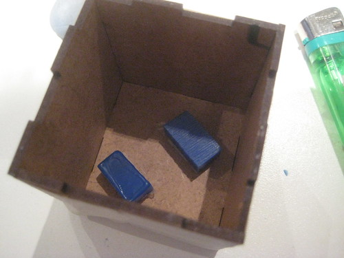
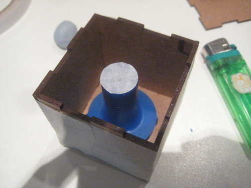
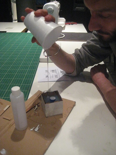
I then mixed up some silicone, trying not to get air in there (tricky) and 'stretch poured' it into the box. I think this help to degas the mixture a little but there were still a lot of bubbles rising up slowly once the pour was complete. I had put a little tape over one end of the master with a small puncture hole in it, in the hope that this will provide a week point in the silicone mold where the plug can break free to release the cast, or possible the wax master too. I'd like to be able to use the mold more than one if at all possible. I am now waiting for this all to set (we are going through a cold snap here so this may take a little longer than usual) before I will remove the wax (mechanically or by melting) and hopefully be able to try a PU rubber cast. Will update here when this happens.

Wednesday, February 27, 2013
Fab Academy: 3D Scanning and Printing
This week's Fab Acadamey assignment was quite straight forward: 3D scan something and 3D print something, preferably the same thing.


However, when it came to exporting the STL, I found that ScanStudio (the NextEngine software) outputted all my various scans superimposed on top of each other. It took me a few days to get round to looking at theis problem, so didn't get to print my scan - will do that when I next get a chance. In the end it turned out that the culprit was a checkbox in the Output (or Save As) window of ScanStudio that needs checking in order to export only the green attached meshes. Having done that, The stl still had some holes in it that ScanStudio couldn't fix (that file is here), so I imported it into Meshlab and used a Poisson reconstruction filter to reconstruct a closed mesh. This always works, but one does lose some of the original level of detail of the scan. That file is here. I also tried the netfabb cloud STL fixing service, which did a much better job (and quick!) of fixing the holes but retaining the original point data. That file is here.
I shall put up photos of the print as and when it is done.
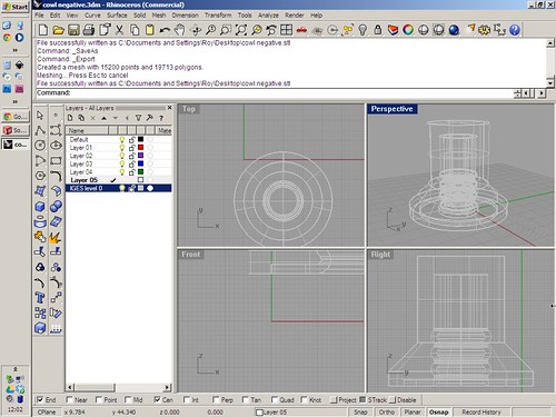
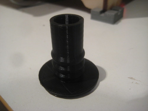
I used our Ultimaker to print a model I had made in Solidworks for a current project - a sheath for a joystick. I also used Rhino to make a negative of the joystick part in the hope that I could directly print a mould for casting a silicone version of the sheath in. The print went fine, but it remains to be seen if this casting method will work! Here is the .stl file for the basic sheath and here is the file for the mould.


The printing was fairly straightforward again, just one failure early on in the first attempt at printing the mould. As Jon in the lab showed me, this was due to the initial z height of the stage being slightly off, so the first layer was effectively printing in midair, not getting a good bond to the build platform. With the second attempt, things went much smoother, and I cranked up the print speed to 150%, approx 70mm/s, with still good results. I like the Ultimaker.


3D Scanning
I have already gotten to grips fairly well with the NextEngine 3D scanner in MAKlab, and have written a tutorial based on my efforts over at Instructables here. I will pop it up in the Fab Academy content archive when I figure out how to get access. I chose to scan a model for Caroline in the lab - she is interested in knots and has modelled some nicely complex forms in plasticine that make great subjects for 3D scanning, because of their complexity and the plasticine is just the right sort of surface to scan quite reliably with the NextEngine. So I did a test single scan followed by a couple of 360 degree scans, with the model in different orientations so that the scanner could get to 'see' every surface - the scanner works on the structured light principle, so projects a laser array onto the object sa you can see in the video below. As a result it is easy for it to miss parts of the model geometry that are in shadow with respect to these laser lines. I've found that a large part of the challenge of 3D scanning is simply rigging the object so that it CAN be scanned! You can see the two orientations I used below.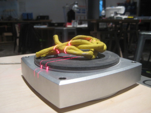

STL Exporting issue
However, when it came to exporting the STL, I found that ScanStudio (the NextEngine software) outputted all my various scans superimposed on top of each other. It took me a few days to get round to looking at theis problem, so didn't get to print my scan - will do that when I next get a chance. In the end it turned out that the culprit was a checkbox in the Output (or Save As) window of ScanStudio that needs checking in order to export only the green attached meshes. Having done that, The stl still had some holes in it that ScanStudio couldn't fix (that file is here), so I imported it into Meshlab and used a Poisson reconstruction filter to reconstruct a closed mesh. This always works, but one does lose some of the original level of detail of the scan. That file is here. I also tried the netfabb cloud STL fixing service, which did a much better job (and quick!) of fixing the holes but retaining the original point data. That file is here.
I shall put up photos of the print as and when it is done.
3D Printing
I used our Ultimaker to print a model I had made in Solidworks for a current project - a sheath for a joystick. I also used Rhino to make a negative of the joystick part in the hope that I could directly print a mould for casting a silicone version of the sheath in. The print went fine, but it remains to be seen if this casting method will work! Here is the .stl file for the basic sheath and here is the file for the mould.
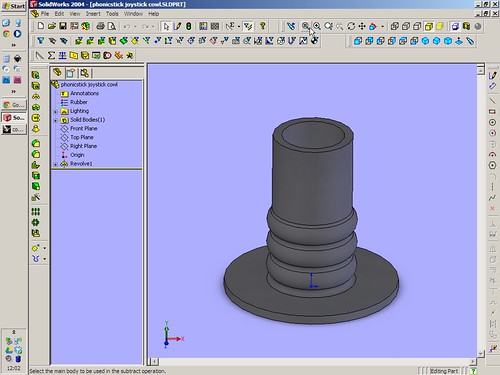
The printing was fairly straightforward again, just one failure early on in the first attempt at printing the mould. As Jon in the lab showed me, this was due to the initial z height of the stage being slightly off, so the first layer was effectively printing in midair, not getting a good bond to the build platform. With the second attempt, things went much smoother, and I cranked up the print speed to 150%, approx 70mm/s, with still good results. I like the Ultimaker.

Wednesday, February 20, 2013
Making a FabISP board
This week's Fab Academy assignment was electronics production: routing a PCB and populating the board with components to produce a FabISP, that is a wee programmer board for programming AVR microcontrollers.
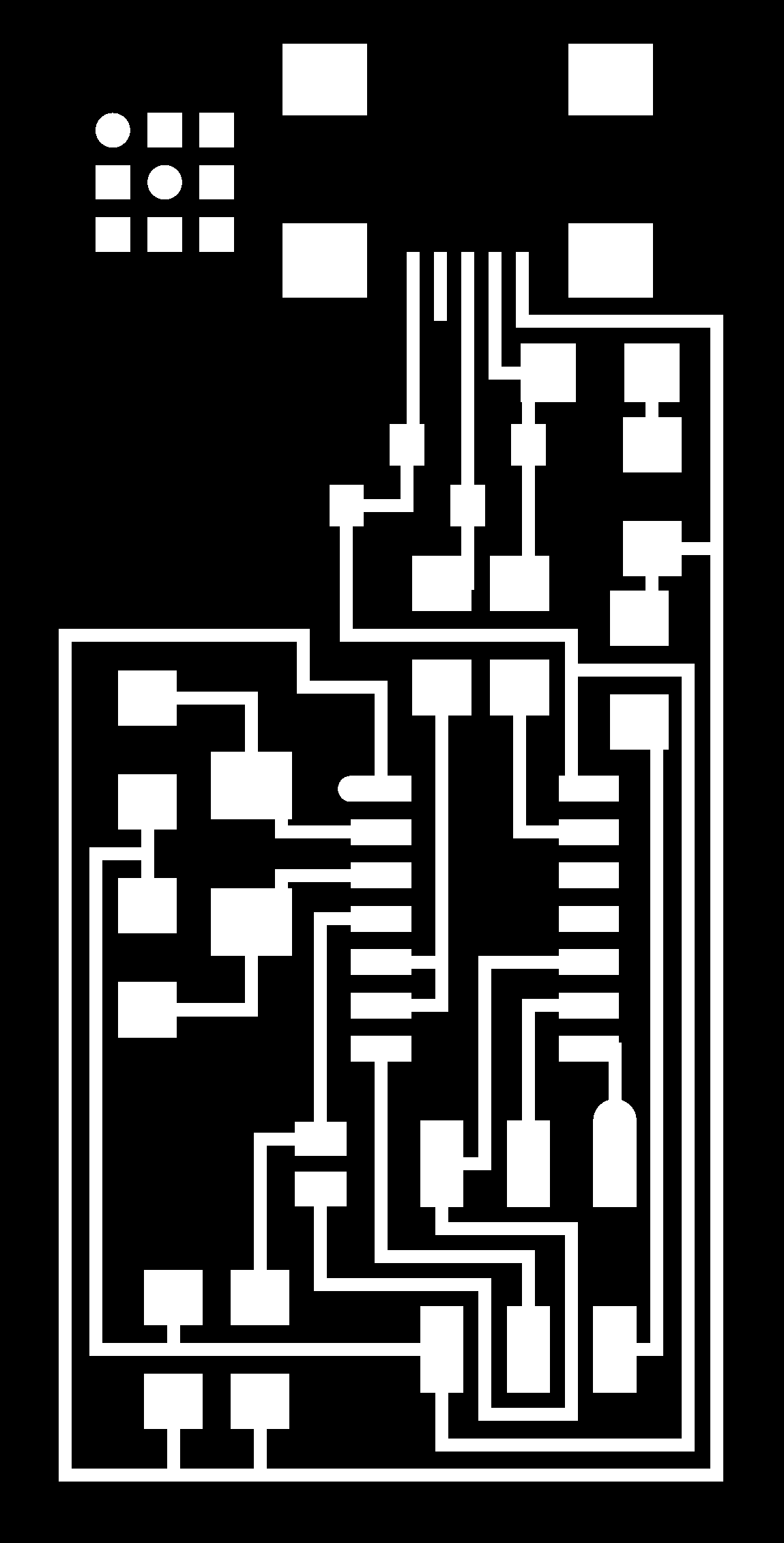
Vcarve is normally great at tracing from a bitmap image such as the .png provided. However it wasn't playing ball for me so I ended up tracing it in Illustrator and exporting a .ai that Vcarve did feel like reading. This method led to a slight error as I'll detail later. (The importing problem solved itself when we restarted the machine later).
So we milled ours using a 0.15mm V shaped engraving bit which gave better results (as suggested by other lab members). I pocketed the routing, so that the mill removed all bits of copper on the board not needed, rather than just cutting the profiles of the traces. I was being cautious with cutting speeds so this did take some time, which we will have to work on (and indeed Loraine managed to get the time down significantly). I was using a feedrate of 4mm/sec, cutting to a depth of 0.15mm, so needing 2 passes as my board wasn't very flat having been taped to a piece of plywood.
I then used a 3.1mm endmill to cutout the board, and went for a way too conservative speed of 1mm/sec with a depth of approx. 1mm. On top of that, we found that Vpanel (the live controller program for the mill) was showing that the mill was cutting much slower even than the speed I specified. The reason for this was the new settings not propogating properly in Vcarve, so I learnt a new quirk of the program there. (Basically, to update tool settings you have to change to a different tool and back again and update the settings).

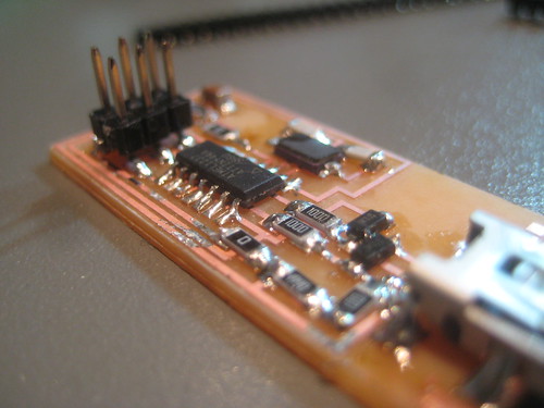
As you might be able to see, my illusrtator traces resulted in the loss of one pad at the USB socket (thankfully it was one of the mechanical pads, rather of any electrical significance) and a little notch being taken out of the perimeter of the board also at the USB socket. The former was fixed with a little superglue at the end.
I found the following soldering method generally worked well for me: Using a flux pen on all pads, then applying solder to the first pad of the component. I then pressed the component in place and on top of that solder and reflowed the solder to tack the component down on its first leg. I then could solder remaining legs almost as normal, albeit with much less solder and occasionally cleaning up with braid. By far the trickiest was the USB socket legs, which I couldn't get flush with the board properly.


Setup
We are having much trouble getting Ubuntu into use in the lab, for various reasons, and most advice has been against attempting to get Fab modules running under a Windows machine that is not online, which is the machine we have connected to the Roland Modela MD40 in MAKlab. So we went with a workflow the experts in the lab are much more familiar with, which is using Vcarve.Vcarve is normally great at tracing from a bitmap image such as the .png provided. However it wasn't playing ball for me so I ended up tracing it in Illustrator and exporting a .ai that Vcarve did feel like reading. This method led to a slight error as I'll detail later. (The importing problem solved itself when we restarted the machine later).
Milling
Thomas had attempted the milling first and found our endmills were not great for the task, burring up the copper quite badly. We were also lacking a really thin one for getting between the traces in the FABisp layout.So we milled ours using a 0.15mm V shaped engraving bit which gave better results (as suggested by other lab members). I pocketed the routing, so that the mill removed all bits of copper on the board not needed, rather than just cutting the profiles of the traces. I was being cautious with cutting speeds so this did take some time, which we will have to work on (and indeed Loraine managed to get the time down significantly). I was using a feedrate of 4mm/sec, cutting to a depth of 0.15mm, so needing 2 passes as my board wasn't very flat having been taped to a piece of plywood.
I then used a 3.1mm endmill to cutout the board, and went for a way too conservative speed of 1mm/sec with a depth of approx. 1mm. On top of that, we found that Vpanel (the live controller program for the mill) was showing that the mill was cutting much slower even than the speed I specified. The reason for this was the new settings not propogating properly in Vcarve, so I learnt a new quirk of the program there. (Basically, to update tool settings you have to change to a different tool and back again and update the settings).

As you might be able to see, my illusrtator traces resulted in the loss of one pad at the USB socket (thankfully it was one of the mechanical pads, rather of any electrical significance) and a little notch being taken out of the perimeter of the board also at the USB socket. The former was fixed with a little superglue at the end.
Populating ('stuffing') and Soldering
This went better than I had expected, being very familiar with thru-hole soldering and very scared of surface mount soldering (I have not steady hands). Being organised and methodical, using tweezers, good light, a magnifier and a PCB vice were all essential.I found the following soldering method generally worked well for me: Using a flux pen on all pads, then applying solder to the first pad of the component. I then pressed the component in place and on top of that solder and reflowed the solder to tack the component down on its first leg. I then could solder remaining legs almost as normal, albeit with much less solder and occasionally cleaning up with braid. By far the trickiest was the USB socket legs, which I couldn't get flush with the board properly.
Improvised headers
The headers required some improvisation as we couldn't get the surface mount headers specified, and they are seemingly almost impossible to find through big UK suppliers. Mine I made using straight thru hole headers, superglued together and the bottom legs bent outwards using pliers and shortened with wiresnips. Quite neat in the end.
Programming
Finally programming, which I failed to do this week as I ran out of time trying to get the programmer for programming the programmer installed. So, another time..Thursday, November 08, 2012


Tuesday, November 06, 2012
Maklab Workshops in November
I'm going to be running a few workshops in Maklab this month:
Thurs 15th 6pm-8pm
Preparing vector artwork for lasercutting (using Illustrator/Inkscape)
£5/£3 members - bring your own laptop with Illustrator or Inkscape on if you wish
Thurs 22nd 7pm-10pm
Glasgow Open Source Hardware Group presents: Using conductive inks - with Mike Shorter and Tom Metcalfe of Dundee University
price TBC - probably £7/£5 members - includes materials
Thurs 29th 6pm-8pm
An introduction to Arduino
£5/£3 members - bring an Arduino and laptop if you have one.
Email me at roy@zero-waste.co.uk to book a place.
Thurs 15th 6pm-8pm
Preparing vector artwork for lasercutting (using Illustrator/Inkscape)
£5/£3 members - bring your own laptop with Illustrator or Inkscape on if you wish
Thurs 22nd 7pm-10pm
Glasgow Open Source Hardware Group presents: Using conductive inks - with Mike Shorter and Tom Metcalfe of Dundee University
price TBC - probably £7/£5 members - includes materials
Thurs 29th 6pm-8pm
An introduction to Arduino
£5/£3 members - bring an Arduino and laptop if you have one.
Email me at roy@zero-waste.co.uk to book a place.
Tuesday, August 28, 2012
More Glad Cafe photos
Patrick Jamieson has uploaded some great photos of the Glad to Facebook here:
https://www.facebook.com/media/set/?set=a.10151055888523347.450221.351164933346&type=1
cheers Pat!

https://www.facebook.com/media/set/?set=a.10151055888523347.450221.351164933346&type=1
cheers Pat!
Monday, August 27, 2012
Maklab is live

Glasgow's first public fablab, Maklab is up and running too! This has been a long time in the making, and is a in a really good setting in the Lighthouse, with excellent generous support from Skirmishes and Creative Scotland. Expect some workshops from me there in the future!
Memberships are £120 + VAT for individuals, and there are LOADS of machines.
Well chuffed again.
Glad Cafe all done
It's been too long. I have been mainly working on the Glad Cafe, which is now truly up and running and it is GREAT to have a nice, friendly evening venue in the south side that isn't a restaurant.
Best Boy Jamie from Conquering Animal Sound (played the first public launch night) took this splendid Instagram:

STV also have some good photos here.
A team of us worked on the interior design, and built two bars, three large pieces of shelving, a whole lot of ballustrading, one chandelier, a bunch of signage and a couple of murals. Main protagonists are Silo, and Gerry of Eggmachine (he once did this, also with Si), with some help from Staci Rowlison on the mural and Bevan Quinn of Modern Standard on sign duties.
The job was supported in no small way by Maklab, who donated some perfect offcuts for the balustrade. A zero-waste job for them!
Well chuffed.
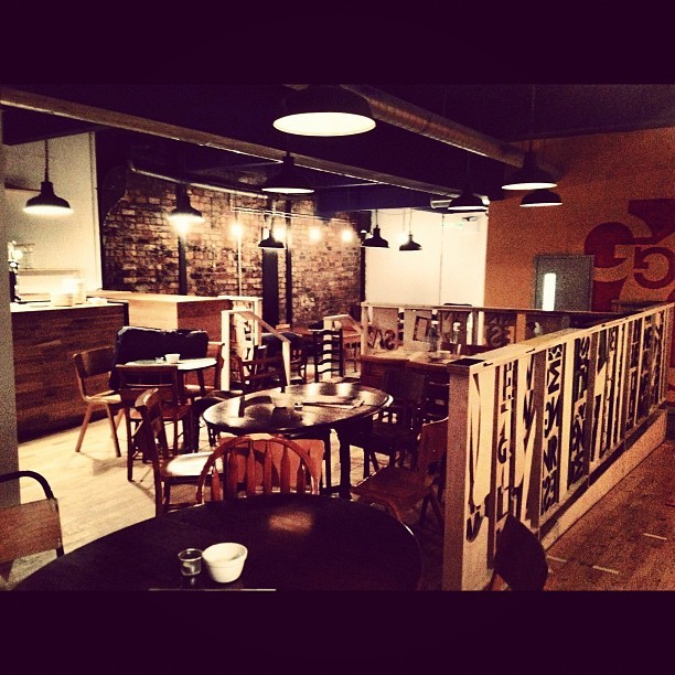
A team of us worked on the interior design, and built two bars, three large pieces of shelving, a whole lot of ballustrading, one chandelier, a bunch of signage and a couple of murals. Main protagonists are Silo, and Gerry of Eggmachine (he once did this, also with Si), with some help from Staci Rowlison on the mural and Bevan Quinn of Modern Standard on sign duties.
The job was supported in no small way by Maklab, who donated some perfect offcuts for the balustrade. A zero-waste job for them!
Well chuffed.
Wednesday, March 21, 2012
The New Aesthetic
This is rather good, from one of the Really Interesting Group chaps:
Video
The New Aesthetic website is here.
Makes me think that the new aesthetic of CNC ply and lasercut things are sympotomatic of this greater trend - another way in which we are speaking the language of robotics.
Video
The New Aesthetic website is here.
Makes me think that the new aesthetic of CNC ply and lasercut things are sympotomatic of this greater trend - another way in which we are speaking the language of robotics.
Monday, March 12, 2012
Mass Making
Last Wedenesday I talked to Glasgow School of Art first years about the maker movement as part of the Forum fro Critical Enquiry (formerly H&C, something i knew nothing of, having been in mech eng lectures, or not at uni at all depending on your point of view).
ANYWAY.
Here are the edited presentation visuals (two I admittedly didn't have the right to publish). It won't make any sense if you weren't there, but I rattled through stuff at an increasingly frantic pace, so this might be useful if you couldn't note down the names of things/links.
I have to thank my friend Stephen Coleman of magical animators Mifundo for invaluable criticism and comments the night before giving this talk!
embed below ->
Mass Making
ANYWAY.
Here are the edited presentation visuals (two I admittedly didn't have the right to publish). It won't make any sense if you weren't there, but I rattled through stuff at an increasingly frantic pace, so this might be useful if you couldn't note down the names of things/links.
I have to thank my friend Stephen Coleman of magical animators Mifundo for invaluable criticism and comments the night before giving this talk!
embed below ->
Mass Making
Monday, September 19, 2011
Maklab day
Mike Vanis and I took the Makerbot along to the Maklab symposium on Friday. It was a good day, with some great workshopping with high school students courtesy of Kathy and Stuart - many thanks, and thanks to Bruce for organising the event. More info at the rather new website here, or on facebook here.
Tuesday, July 12, 2011
Today's 3D printing
Today I have printed a part for Gaz and Jo's Clio car, and another part for Neel#s showerhead clip system, and am now tweaking the PID settings on the printer in the hope that might fix the extruder-not-getting-to-target-temperature problem. Slideshow below:
Wednesday, May 04, 2011
MAKIT this Friday
Come along to the MAKIT maker's meetup this Friday, featuring a mobile
FABLAB from Holland! The laser cutter/3d printer/vinyl cutter endowed
van will be in the Gorbals this Friday from 10am - 5pm at:
St Francis Community Center, 405 Cumberland Street. Gorbals. Glasgow. G5 0YT.
Please pass this around to anyone that might be interested in coming along.
More details at www.skirmishes.org/?p=292
Bring an idea of something to make, or a
project to share that shows how useful digital fabrication can be! We
would like to make this event into a handy meet up for the wide
community of makers in Glasgow, to share, learn and make, in the same
way that we could in the Glasgow Fablab (AKA Maklab). It will also be
a great opportunity for those who are unfamiliar with these tools and
methods to experience the fablab and get a sense of what it could be
used for.
The event is an informal drop in and forms part of Skirmishes Edge
City design charette being held on the same day
[http://www.skirmishes.org/?p=263]. I shall be hanging round the
fablab all day though, documenting things and gathering ideas for
establishing the Glasgow Fablab, so do come along and say hello.
FABLAB from Holland! The laser cutter/3d printer/vinyl cutter endowed
van will be in the Gorbals this Friday from 10am - 5pm at:
St Francis Community Center, 405 Cumberland Street. Gorbals. Glasgow. G5 0YT.
Please pass this around to anyone that might be interested in coming along.
More details at www.skirmishes.org/?p=292
Bring an idea of something to make, or a
project to share that shows how useful digital fabrication can be! We
would like to make this event into a handy meet up for the wide
community of makers in Glasgow, to share, learn and make, in the same
way that we could in the Glasgow Fablab (AKA Maklab). It will also be
a great opportunity for those who are unfamiliar with these tools and
methods to experience the fablab and get a sense of what it could be
used for.
The event is an informal drop in and forms part of Skirmishes Edge
City design charette being held on the same day
[http://www.skirmishes.org/?p=263]. I shall be hanging round the
fablab all day though, documenting things and gathering ideas for
establishing the Glasgow Fablab, so do come along and say hello.
Saturday, May 15, 2010
What the real big society means for the economy, charities and copyright
Two excellent mini docs just posted to the Guardian videostream from Heydon Prowse and William Pine:
http://www.guardian.co.uk/environment/video/2010/may/11/ethical-living-diy-big-society
http://www.guardian.co.uk/environment/video/2010/may/12/ethical-living-real-big-society-two
These make essential viewing in my opinion, if only to come some some way to understanding where I'm coming from: ie. spending my time and earnings on the sometimes seemingly pointless area of open design. Its the empowerment stupid.
This is going out as what one might call a three line whip, being blogged on the Slog, here and Censta simultaneously. Annoying to have to do it thrice, I wish there was a way to post to several blogs at the same time, or that Censta would get more feed friendly.
http://www.guardian.co.uk/environment/video/2010/may/11/ethical-living-diy-big-society
http://www.guardian.co.uk/environment/video/2010/may/12/ethical-living-real-big-society-two
These make essential viewing in my opinion, if only to come some some way to understanding where I'm coming from: ie. spending my time and earnings on the sometimes seemingly pointless area of open design. Its the empowerment stupid.
This is going out as what one might call a three line whip, being blogged on the Slog, here and Censta simultaneously. Annoying to have to do it thrice, I wish there was a way to post to several blogs at the same time, or that Censta would get more feed friendly.
Tuesday, March 23, 2010
Future Craft Exhibition
Openthing and Niftymitter will be appearing in an exhibition at DJCAD as of Thursday, entitled Futurecraft. The exhibition marks the end of the Past Present and Future Craft research project, and kicks of their Scotland wide Craft Festival. Find it on Level 5 of the Matthew building.
Slides from GSA and Strathclyde talks
I gave a short talk a couple of weeks ago at Strathclyde uni for DMEM students, and then at the GSA for Vis Com students. It was good fun, and I was paired up with Emlyn of Central Station at the GSA talk, which was highly interesting. Check out his work at central station here.
The slides for the presentation are downloadable here.
The slides for the presentation are downloadable here.
Subscribe to:
Posts (Atom)

